Shaders Explained: Dithering

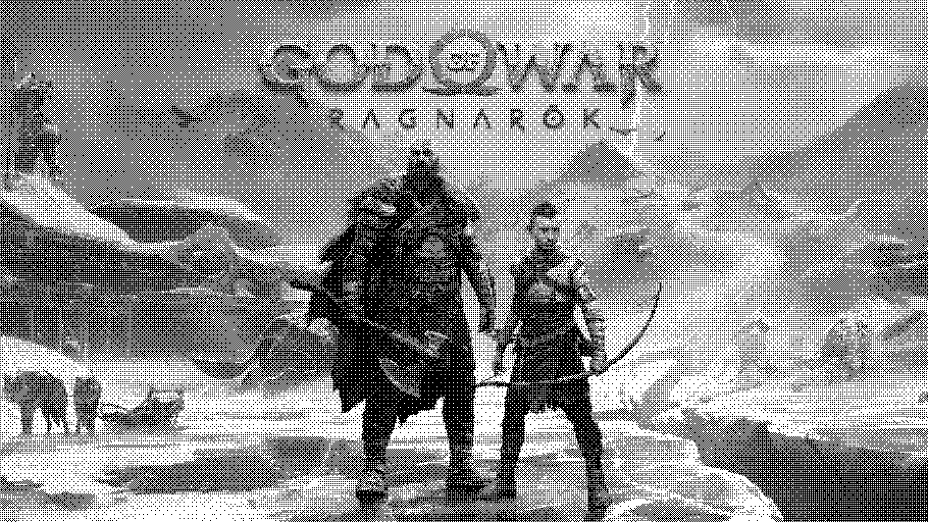
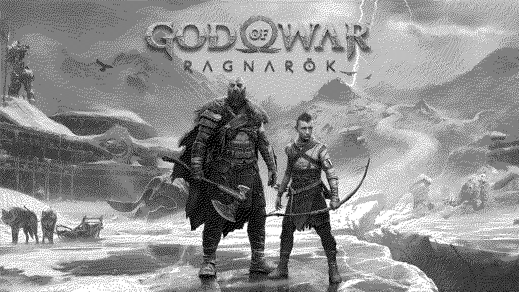
Three months ago I launched a small app on the App Store which allows users to edit photos in a stylish old-school way. The processing technology is called dithering. It is a very old technic from the days when computers were capable to show very limited amount of colors. But developers and artists always wanted to go further existing software and hardware limits so they invented such algorithms. Dithering makes images look like they use much extended color palette than they actually has and missing shades are emulated through placing pixels with allowed colors in proper way. Look at the image in the header. Central part of it uses only black and white pixels and not a single grey one but because the amount of black and white pixels is different in different areas the whole image looks like it uses much extended grayscale color palette. In this post I’ll explain how it works and how to implement it in Metal.
DISCLAIMER! I used God of War Ragnarök official art to show how dithering algorithms work. All the rights for it belongs to Sony and I hope Sony allows to use this image for demonstration purposes. Nevertheless it is a wonderful game!

Why Dithering?
You may wonder why do we need to mimic missing colors in 2022 when modern displays can show millions of colors? The first answer is of course old-school vibes which we can create using old algorithms for color management :) This is what my Dither app do. The second reason is to reduce file size. You actually see dithering a lot even today while laughing at memes on Twitter. GIF format uses only 256 colors to make files small in size and shading is done via ordered dithering.
Ordered dithering is way more popular then an unordered alternative. Because it requires less processing power. Also it can be easily parallelized and so we can run it on GPU in realtime for video frames or camera input without frame drops. Unordered dithering looks slightly better but it is an error diffusion algorithm. That means it is linear by design and for a long time it was considered impossible to run it in parallel. Because pixels are processed in order and on each step error is calculated and propagated to neighboring pixels. So theoretically color of the very last pixel of the image depends on the first one. But researches don’t like the word “impossible” and as GPU processing becomes standard for image processing they invented parallel algorithms for error diffusion dithering. And I implemented one of them in Metal shader.
Though error diffusion dithering is more interesting from engineering perspective lets start from the simple ordered algorithms!
Ordered Dithering
Ordered dithering was used on a variety of old computers and game consoles. It is perfectly suited for GPU processing where each pixel processed individually in a highly parallelized way.
To implement it we will need input image, color palette of allowed output colors and a matrix which we will apply to input image before trying to find the closest color from palette.
Matrix for ordered dithering is called index matrix or Bayer matrix and it can be constructed recursively from the root 2x2 matrix according to formula from this Wikipedia article.
For performance reason I used predefined matrices with 2x2, 4x4 and 8x8 sizes also from Wikipedia. Here they are:
enum Matrix {
    case matrix2x2
    case matrix4x4
    case matrix8x8

    var array: [Float] {
        switch self {
        case .matrix2x2:
            return [
                0, 2,
                3, 1,
            ].map { $0 / 4 - 0.5 }
        case .matrix4x4:
            return [
                0, 8, 2, 10,
                12, 4, 14, 6,
                3, 11, 1, 9,
                15, 7, 13, 5,
            ].map { $0 / 16 - 0.5 }
        case .matrix8x8:
            return [
                0, 32, 8, 40, 2, 34, 10, 42,
                48, 16, 56, 24, 50, 18, 58, 26,
                12, 44, 4, 36, 14, 46, 6, 38,
                60, 28, 52, 20, 62, 30, 54, 22,
                3, 35, 11, 43, 1, 33, 9, 41,
                51, 19, 59, 27, 49, 17, 57, 25,
                15, 47, 7, 39, 13, 45, 5, 37,
                63, 31, 55, 23, 61, 29, 53, 21,
            ].map { $0 / 64 - 0.5 }
        }
    }
}
The matrix is passed as an array of Floats to shader according with matrix size as ushort2 (SIMD2<UInt8> in Swift terminology). Palette is also an array of float3 (SIMD3<Float>) colors, each channel of which is in 0...1 range. Since it is a pointer to MTLBuffer with array in it we also need to tell the shader its size.
The full shader is rather simple:
[[ kernel ]]
void orderedDither(texture2d<float, access::read> source [[ texture(0) ]],
                   texture2d<float, access::write> destination [[ texture(1) ]],
                   constant float* matrixValues [[ buffer(0) ]],
                   constant ushort& matrixSize [[ buffer(1) ]],
                   constant float3* palette [[ buffer(2) ]],
                   constant ushort& paletteCount [[ buffer(3) ]],
                   const ushort2 tid [[ thread_position_in_grid ]]) {
    const float4 sourceColor = source.read(tid);

    const ushort2 matrixPosition = tid % ushort2(matrixSize);
    const float matrixValue = matrixValues[matrixPosition.y * matrixSize + matrixPosition.x];
    const float3 destinationColor = closestColor(saturate(sourceColor.rgb + float3(matrixValue)), palette, paletteCount);

    destination.write(float4(destinationColor, sourceColor.a), tid);
}- First we take the color of pixel from the source texture;
- Then find the corresponding position from matrix;
- Take the matrix value at this position;
- Sum source color and matrix value, saturate it so it will be in
0...1range; - Find the closest color to this summed value from palette;
- And write it to destination texture.
There are several implementations of closestColor function available on the internet. For black and white dithering you may just use Metal’s step function and for color dithering the simple vector distance will work fine. Some developers suggest to convert colors to LAB color space and then calculate distance between current color and palette colors. I’ll omit implementation of this function here.
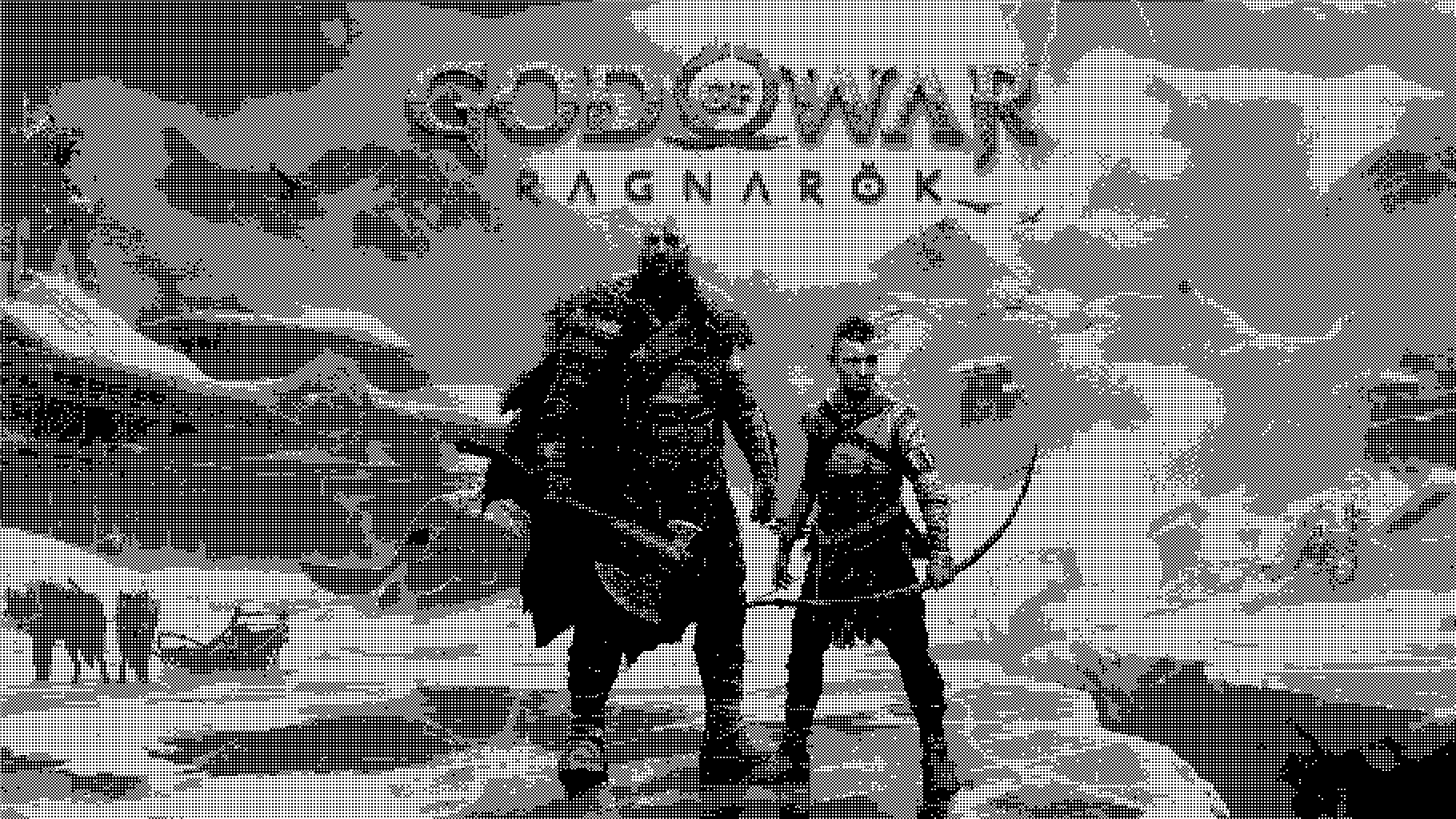
For black and white palette we will have God of War Ragnarök poster as it was printed on slow and loud matrix printer.
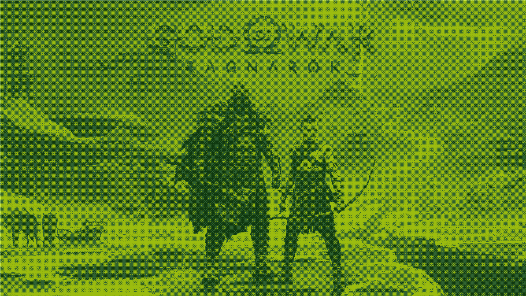
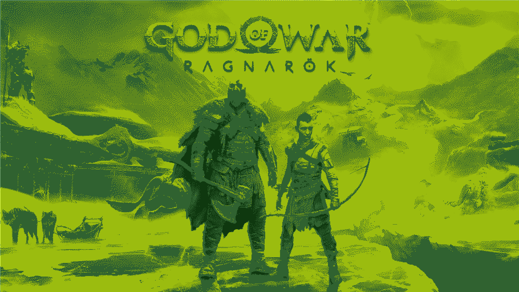
And what if we would have GameBoy HD console with its traditional greenish color palette which can run this state of the art game?
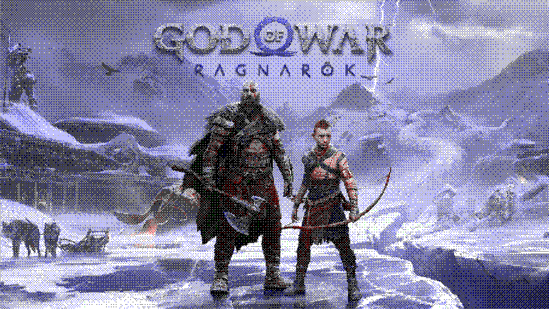
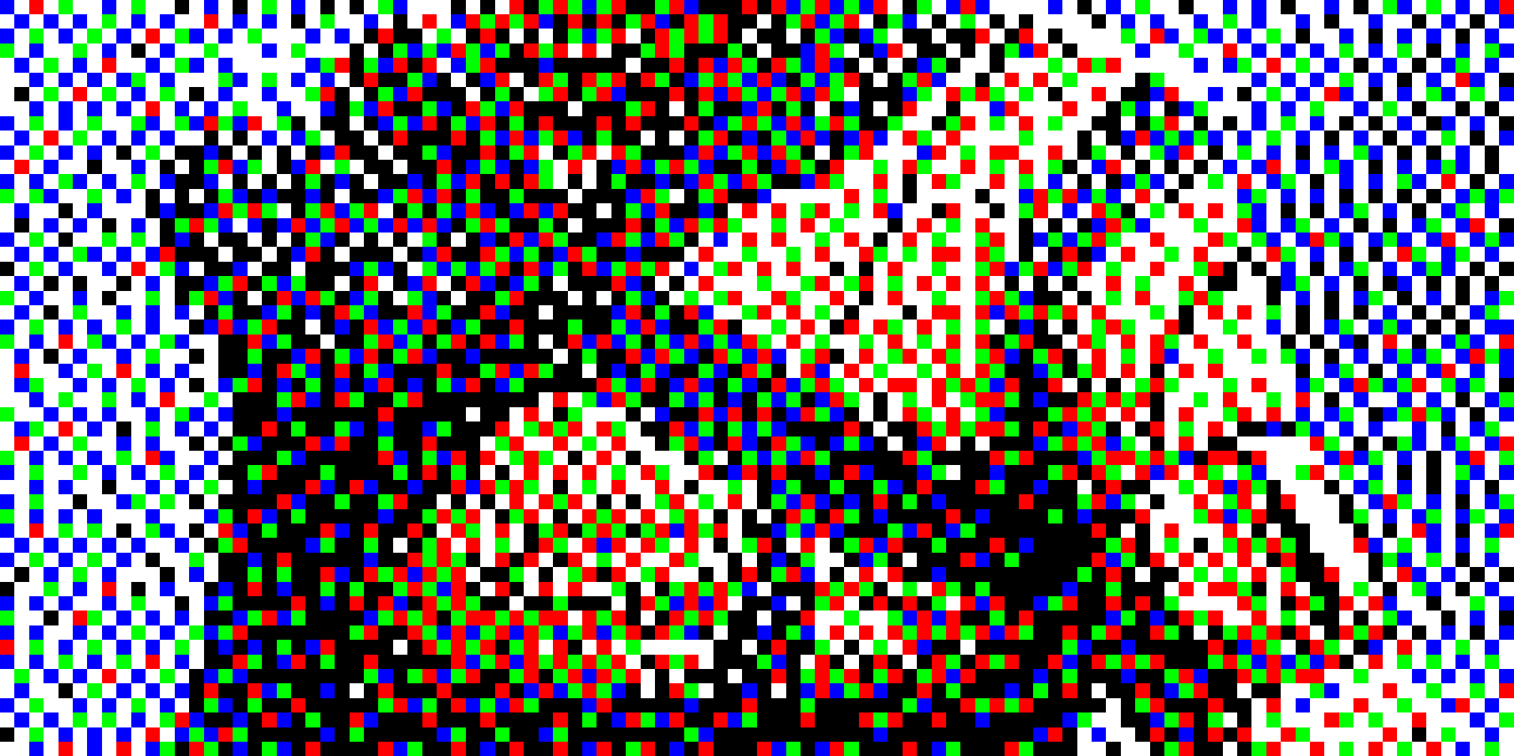
We are not limited in making only grayscale images with applied tint to it. Any color palette can be used. Here is the same poster which uses only black, white, red, green and blue colors (BWRGB).
Notice how matrix pattern is clearly visible in all these images. The same pattern you may see on GIF images. For smaller matrix size the pattern become so repetitive that it ruin a lot of image details. Here is the black and white dithered image with 2x2 matrix. For the previous images I used 8x8. Here you can see how the shapes of mountains on background become indistinguishable with the sky.
But enough for ordered dithering! It was really a trivial shader. Lets try to accomplish more challenging task and apply linear algorithm to GPU processing. But first we need to understand how Metal dispatching works.
Few Words About Dispatching
When you schedule tasks to GPU you need to tell Metal how much threads it need to run to process it. For vertex/fragment shaders in base case you use this function
func drawPrimitives(
    type primitiveType: MTLPrimitiveType,
    vertexStart: Int,
    vertexCount: Int
)
Metal will schedule as many threads as you declare in vertexCount variable for vertex shader and then after rasterization step schedule a thread for each pixel which is covered by your geometry.
When you program GPU pipelines you may think that all the vertices will be processed in parallel and then all the pixels also. That is what GPU was created for after all! But the reality is slightly different. Processors has certain number of cores and even the most powerful unit has its own limits.
For example Apple M1’s GPU have 8 cores, each of which contains 16 execution units and every execution unit has 8 arithmetic logic units (ALUs). So the total number of ALUs is 1024 but each ALU can process 24 threads simultaneously. It doesn’t mean that you can expect that all 24K threads will be scheduled for you task because iOS also uses GPU for UI rendering and some background work. But it clearly shows the difference between CPU and GPU performance for parallel execution tasks.
Render pipeline doesn’t give programmer ability to customize dispatching but compute pipeline does. MTLComputeCommandEncoder has two dispatch methods
func dispatchThreadgroups(
    _ threadgroupsPerGrid: MTLSize,
    threadsPerThreadgroup: MTLSize
)

func dispatchThreads(
    _ threadsPerGrid: MTLSize,
    threadsPerThreadgroup: MTLSize
)
Size of the grid is the amount of threads scheduled for execution. Grid can be of 1D, 2D or 3D size. For image processing we usually use 2D grids for width and height of processed image and run a separate thread for each pixel. Threads in grid are split into thread groups each of which is split into SIMD groups. These methods of compute encoder allow you to fine tune how much threads will be in each thread group and how much threadgroups will form the entire grid. You may even dispatch a single thread for the whole GPU task and execute a fully linear algorithm as you do it usually in Swift on CPU. But we won’t do this in our next shader :)
Combining threads to SIMD and thread groups has another advantage. You can initialize shared memory for thread group or SIMD group right inside shader code and it will be shared across threads in group. Also you may set a barrier for memory access so that every thread inside group will wait for other threads to come to this point. And they will continue only after all the threads will execute barrier function. This is waht we will use for unordered dithering.
Error Diffusion Dithering
As I told earlier error diffusion dithering algorithms or simply unordered dithering propagate error from one pixel to neighboring ones. There are plenty of these algorithms but the main difference between them is in how error is distributed to neighbors. You may find several examples of them in this article which I used as a starting point for my app.
We will implement the most popular algorithm named after its authors Floyd-Steinberg Dithering. To illustrate it lets consider we have grayscale image which we want to convert to black and white dithered image. So our pixel has only one channel and we need to convert its value to zero or one.
Here currently processing pixel is noted as (XX) and numbers around it is how much of error we propagate to neighbors.
      (XX)  7/16
3/16  5/16  1/16
Error is simply the difference between our pixel value and closest value from palette. In our case error will lie in -0.5...0.5 range. If pixel value is 0.4 the error will be 0.4 and if it is 0.6 the error will be -0.4. After calculating the error we propagate 7/16 of it to the right pixel and other 9/16 to three bottom pixels. Summing these values you’ll see that we propagate the whole error (16/16) to neighbors.
This algorithm can be described in 7 steps:
- Take current pixel color;
- Add error already propagated from previous pixels to it;
- Find closest color from palette to this summed value;
- Calculate the difference between this value and the closest color, it will be the new error;
- Assign closest color to current pixel;
- Propagate error to neighboring pixel according to algorithm;
- Repeat from step 1 for next pixel.
As you see this algorithm is linear. The error propagated from first pixel to the next one is used to find the new color for the second pixel. We even can’t find all the errors first and then calculate the pixel colors from them in parallel. Because the error from previous pixel has impact on the error value of current one. But notice that error is propagated only to neighboring pixels, so we can wait when the first thread will go a little bit further and calculate all the required errors. And then we’ll start a second thread. Here (XX) is the first thread and (YY) is the second. And all the already processed pixels marked as (..).
(..)  (..)  (..)  (XX)  7/16
(YY)  (..)  3/16  5/16  1/16
When the first thread processed three pixels the second thread can start execution because the first one assigned all the errors for the right pixel of YY thread. So we actually can run them simultaneously! When YY thread will finish processing of the first pixel in a row the XX thread will go one pixel further and YY will have all the necessary data to continue processing.
I found this algorithm implemented in OpenCL here and if you want to have better understanding of it take a look at this article. I will focus on its Metal implementation but not the algorithm itself.
Lets dive right into it first and then I’ll explain the details.
[[ kernel ]]
void floydSteinbergDither(texture2d<float, access::read> source [[ texture(0) ]],
                          texture2d<float, access::write> destination [[ texture(1) ]],
                          device float3* errorsBuffer [[ buffer(0) ]],
                          constant float3* palette [[ buffer(1) ]],
                          constant ushort& paletteCount [[ buffer(2) ]],
                          const uint threadIndex [[ thread_position_in_grid ]],
                          const uint gridHeight [[ threads_per_grid ]]) {
    const int width = int(source.get_width());
    const int height = int(source.get_height());

    const int startX = int(threadIndex) * -3;
    const int startY = int(threadIndex);

    for (int x = 0; x < (width + int(gridHeight) * 3); x++) {
        const int2 position = int2(startX + x, startY);
        const bool isXInside = position.x >= 0 && position.x < width;
        const bool isYInside = position.y >= 0 && position.y < height;
        if (isXInside && isYInside) {
            const float3 readError = errorsBuffer[position.y * width + position.x];
            const float4 sourceColor = source.read(uint2(position));
            const float3 errorColor = saturate(sourceColor.rgb + readError);
            const float3 destinationColor = closestColor(errorColor, palette, paletteCount);
            destination.write(float4(destinationColor, sourceColor.a), uint2(position));

            const float3 writeError = errorColor.rgb - destinationColor;

            if (position.x < width - 1) {
                errorsBuffer[position.y * width + position.x + 1] += writeError * (7.0f / 16.0f);
            }

            if (position.y < height - 1) {
                const int baseOffset = (position.y + 1) * width + position.x;
                if (position.x > 0) {
                    errorsBuffer[baseOffset - 1] += writeError * (3.0f / 16.0f);
                }

                errorsBuffer[baseOffset] += writeError * (5.0f / 16.0f);

                if (position.x < width - 1) {
                    errorsBuffer[baseOffset + 1] += writeError * (1.0f / 16.0f);
                }
            }
        }

        threadgroup_barrier(mem_flags::mem_device);
    }
}
First of all we pass error buffer to shader. Notice device attribute near errorBuffer parameter in shader signature. It means that memory allocated for this buffer will be in the device address space and can be visible for all the threads no matter which thread group they are dispatched to. Other buffers are in constant address space and so can’t be writable.
Also notice that we use [[ thread_position_in_grid ]] and [[ threads_per_grid ]] modifiers here. Compute shaders can give you all the information about which SIMD group and thread group they are in as well as the size of these groups. So you can write any custom logic using this information if you want to make some kind of interaction between threads in different groups.
Here each thread process a single row of pixels of our image. In Metal we can’t simply put threads in waiting state (or maybe I don’t know how to do it), so all the threads start execution simultaneously but with -3 offset from previous one. So all the threads starting from the second will start execution outside image bounds.
Then we iterate in for-loop through all the pixels in a row and if we are inside image bounds perform error calculation and assign pixel color from palette to destination texture. Also we update error stored in the buffer so that the next threads will be able to find the final calculated error there when they start processing theirs pixels.
The most interesting part is the final line inside for-loop
threadgroup_barrier(mem_flags::mem_device);We have a lot of logic inside if (isXInside && isYInside) statement. So for bottom rows of our image this part of code won’t be executed for a certain amount of time while they are outside the image bounds, these threads can get ahead of the previous ones and we can start processing bottom pixels before all the required error for them is calculated and stored in buffer. That’s why we use barrier here, and these out of bounds threads will wait when currently processing threads will finish all the error calculating. mem_flags::mem_device means that they need to wait while device memory will be written. Remember that errors buffer is lied in this address space.
And here is the result! God of War Ragnarök art processed with Floyd-Steinberg dithering. There are no patterns there because each pixel calculated with different amount of error propagated to it. Also you may see that in the third image which used BWRGB colors Atreus’ armor is more yellow than in ordered dithered image. But there is no yellow color there BOY! Check the last image if you don’t believe me :) Error diffusion algorithms preserve color information better because all the unused color data for pixel is stored in error and propagated to other pixels.

Performance Notice
If you followed carefully along this post you saw that Floyd-Steinberg algorithm is not very efficient. We do a lot of unnecessary work there while processing out-of-bounds pixels and wait for in-bounds pixels to finish processing. This is because error diffusion algorithms are not made for GPU and can perform better on CPU in a single thread with way more processing power. I didn’t make measurements though :)
But sometimes you need to put such a linear algorithms inside GPU pipelines and you have two options to do it:
- Make a CPU stop inside GPU processing. You can make two command buffers with CPU step between them or use
MTLEventto stop GPU execution, perform calculations on CPU and then turn back to GPU execution; - Try to apply algorithm to GPU processing even in a not efficient way.
With CPU stop there may be a lot of troubles. First of all you pipeline architecture may not allow to make another command buffer. For example you use node architecture for processing and each node receives already created command buffer and schedule tasks to it. You’ll need to change all your architecture to make second buffer just for one edge case. MTLEvent on the other side while allow you to use single command buffer, can make a huge impact on pipeline execution time.
Since GPU programming is all about performance you need to measure any single case and choose the best option for you. But sometimes you will find that not efficient GPU algorithm performs better than highly efficient CPU one just because you don’t need to make a switch between processors.
That’s all for now! Hope that you enjoy this long post and it will help you to make stunning results in you apps using Metal. If you have any questions feel free to ask them via email contact@mtldoc.com or connect via Twitter @petertretyakov.
Thank you for reading!